I wanted to build a 3D model of a river valley, like this:
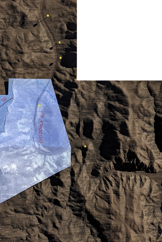
using my SnapMaker 350’s laser cutter.
Its really a 4 part process:
Step 1: create a STL file
Step 2: make a physical model from it (3D print or laser cut)
Step 3: assemble each tile
Step 4: put the tiles in a frame (not shown here)
Creating the STL file
An easy way to do this is to use TouchTerrain.
But the online Elevation Data Sources you can choose from don’t have high enough resolution (outside USA).
So I used the standalone version from https://github.com/ChHarding/TouchTerrain_for_CAGEO
I used it to process a tif file, containing a 5M DEM I got from ELVIS: https://elevation.fsdf.org.au/
Those are .asc files; I used QGIS to merge them then export a .tiff.
The trick is to choose suitable dimensions for your output device. I’m using a Snapmaker 350, laser cutting A3 sheets of cardboard, and happy enough to use a dozen or so sheets per “tile”.
For my output device – a laser cutter – a tile width of 160 works well (I get 2 rows of slices per page), and for my model I’m using 5 tiles wide by 6 tiles high.
(I could use a tile width of say 340mm in my SnapMaker – and thus fewer tiles – but the corresponding STL file would then be large enough to kill Slicer. So 160mm tiles it is.)
TouchTerrain_standalone.py runs pretty quickly (tens of seconds), on my tiff, doing a single tile.
My cardboard purported to be 0.85mm thick. It was actually 0.82mm thick. So an important preliminary is to measure/verify the thickness of your cardboard yourself. If you do this, then when you start on a new tile, you can use a different cardboard thickness (for example, a thin cardboard for tiles you want finer detail, versus thicker cardboard for flat/boring terrain)
With a 5M DEM, I could probably use something half that thickness (with little change in processing time, provided I could cut it in a single pass ie halve the number of passes).
Once you have an STL file, there are lots of programs you could use to render it on your computer (though there is no need to do so).
Making the physical model
I’ve got a Snapmaker 350, which can do 3D printing, but also laser cutting.
I chose to laser cut the model on sheets of cardboard, to avoid using lots of filament.
SnapMaker’s Luban software expects an SVG file, so we need to go from STL to SVG somehow. We can do that using PDF as an intermediate format.
Slicer for Fusion 360 can convert STL to nicely arranged slices, output as PDF.
To begin, import your STL file. You should see a 3D rendering of it.
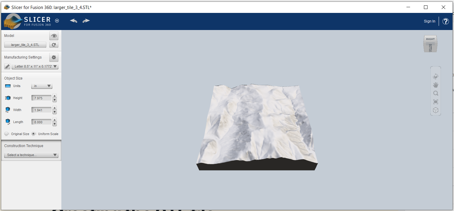
Slicer for Fusion 360 is less than ideal in that it is no longer maintained, and crashes if the STL file is large (eg 50MB), though 20MB STL files work OK.
Define the material:
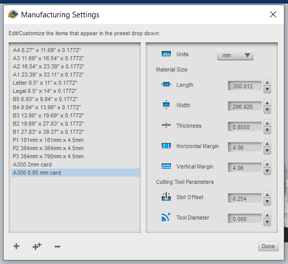
For width, we use A3 width; for height, the Snapmaker’s 350mm. Thickness is that of our cardboard.
Set the object size to its original size; it should match what you got out of TouchTerrain. After choosing the construction technique “Stacked Slices”, you should see something like:
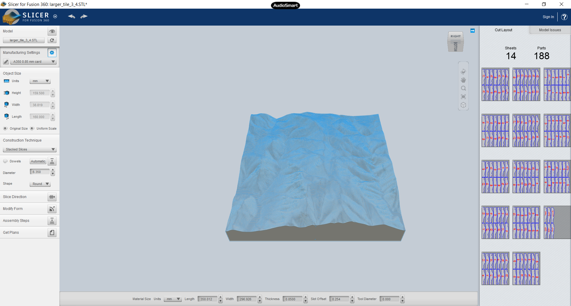
Then press the “Get Plans” button, choose file type PDF, then hit “Export to my Computer” button.
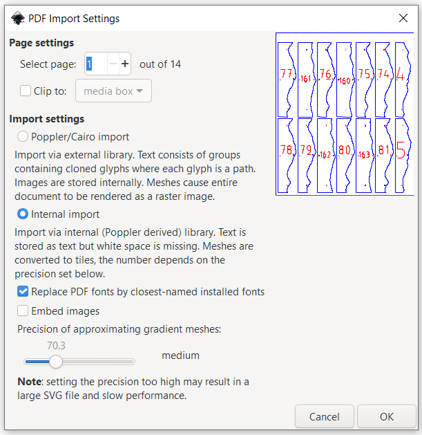
We’re done with the slicer. Now we can use Inkscape to convert the PDF pages to SVG. Import the PDF (a page at a time); be sure to uncheck “embed images”:
In Document Properties, you want the same custom page size of 297×350. Position the objects on the page.
There’s a rectangular path surrounding all the slices. Delete that, which I find easiest to do in the XML editor.
Save the SVG file, and you are done in Inkscape.
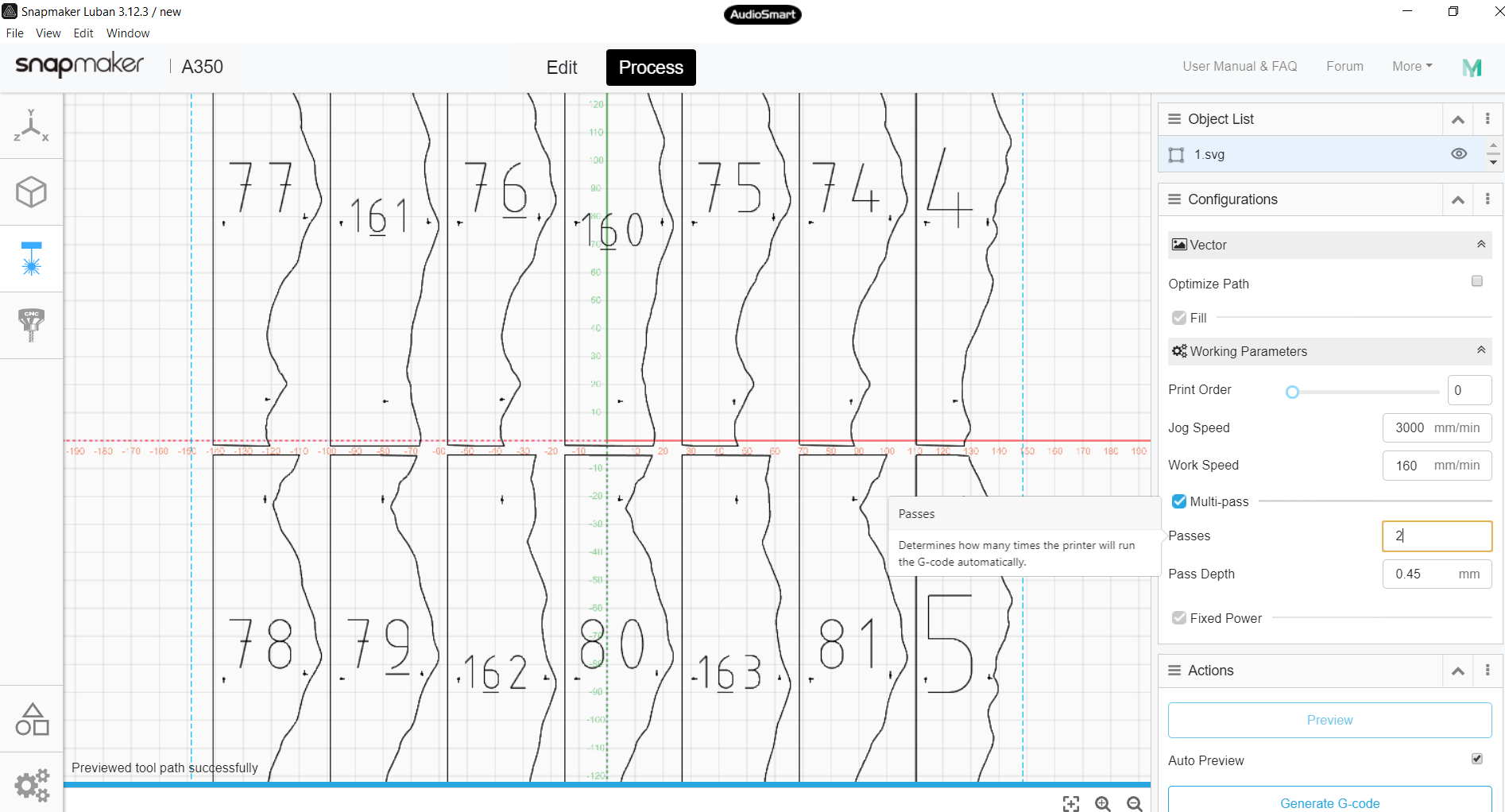
To print using SnapMaker, we use Luban to create gcode from the SVG.
In Luban, choose the laser cutter, the “Add” the svg. Change the width to 297, then hit “Process”.
For my 0.82mm cardboard, I do 2 passes at 0.45:
Now you can “Generate G-code” and “Export G-code to file” to put it on a USB stick you can insert in SnapMaker.
I won’t go into the operation of SnapMaker here, but just make 2 points.
First, its thickness setting adjusts in 0.1mm increments, so for my 0.82mm cardboard, I used 0.8mm.
Second, since its a tight fit on the page, its worth doing “run boundary” before starting the job.
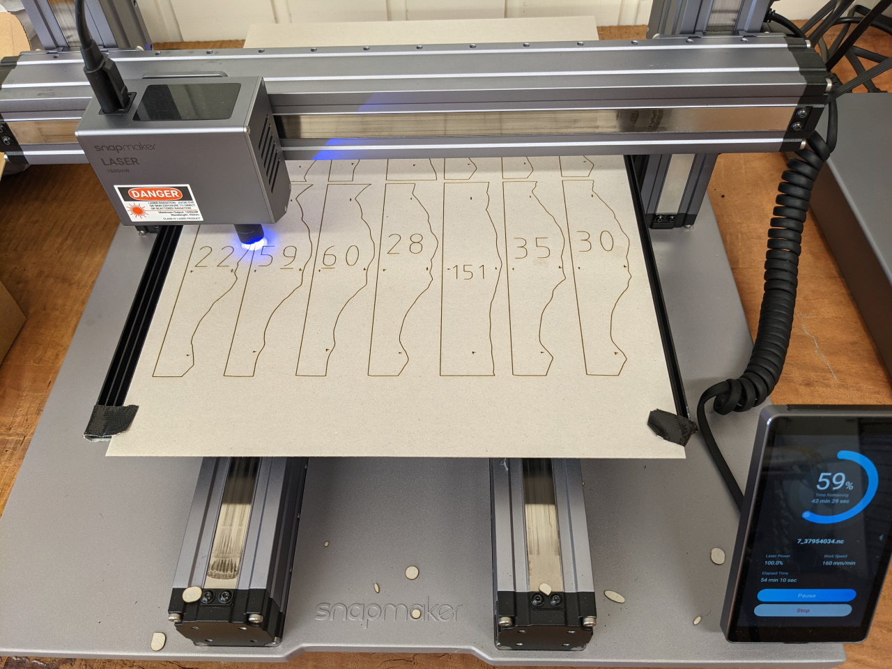
It takes around 90 mins in total per laser cut page (ie for the 2 passes), using a work speed of 170mm.
A note on materials. I sourced my cardboard on eBay. For A350 users in Australia, I’d recommend https://www.ebay.com.au/itm/181782570520. Note that it is advertised as being 0.85mm thick, but I found it to be more like 0.8245. Make sure you measure your cardboard thickness!
Assembling the tile
With my cardboard and model, there are 188 slices per tile, printed over some 13 pages. Once you’ve sorted the tiles into the correct order, you need a way to hold them together.
Slicer for Fusion 360 makes a hole in each tile which you can thread a rod through (the size of the hole depends on what you specified).
I’d recommend 0.5mm rod, of brass (https://www.ebay.com.au/itm/274477438377) or steel (https://www.ebay.com.au/itm/274477406664). Brass is harder to thread since it is more bendy, but easier to cut. Steel is probably better, and you can easily cut it with pliers.
You can have Slicer make a larger hole for a Bunnings 6.3mm aluminium rod, which is a lot more rigid, but then you need to use a hacksaw to cut.
I’m happy with the 0.5mm rod. With the tiles sitting on a wooden base, gravity keeps them flat.